¶ Features
- Ublox GNSS
- Messaging
- ShortRange Advertisement
- ShortRange Scanning
- Contact tracing
- WiFi Scanning
- LR11xx GNSS
- Movement detection
- Flash storage
- Acoustics
- Magnetic switch
- Hibernation mode
- Satellite communication
- Fence monitoring
- Power supply
- S-Band Satellite LoRaWAN
- Cardiac Monitoring Device
- Open Sky detection
- VHF
- Drop-off
- Outdoor Detection (for Pangolin)
- Switch
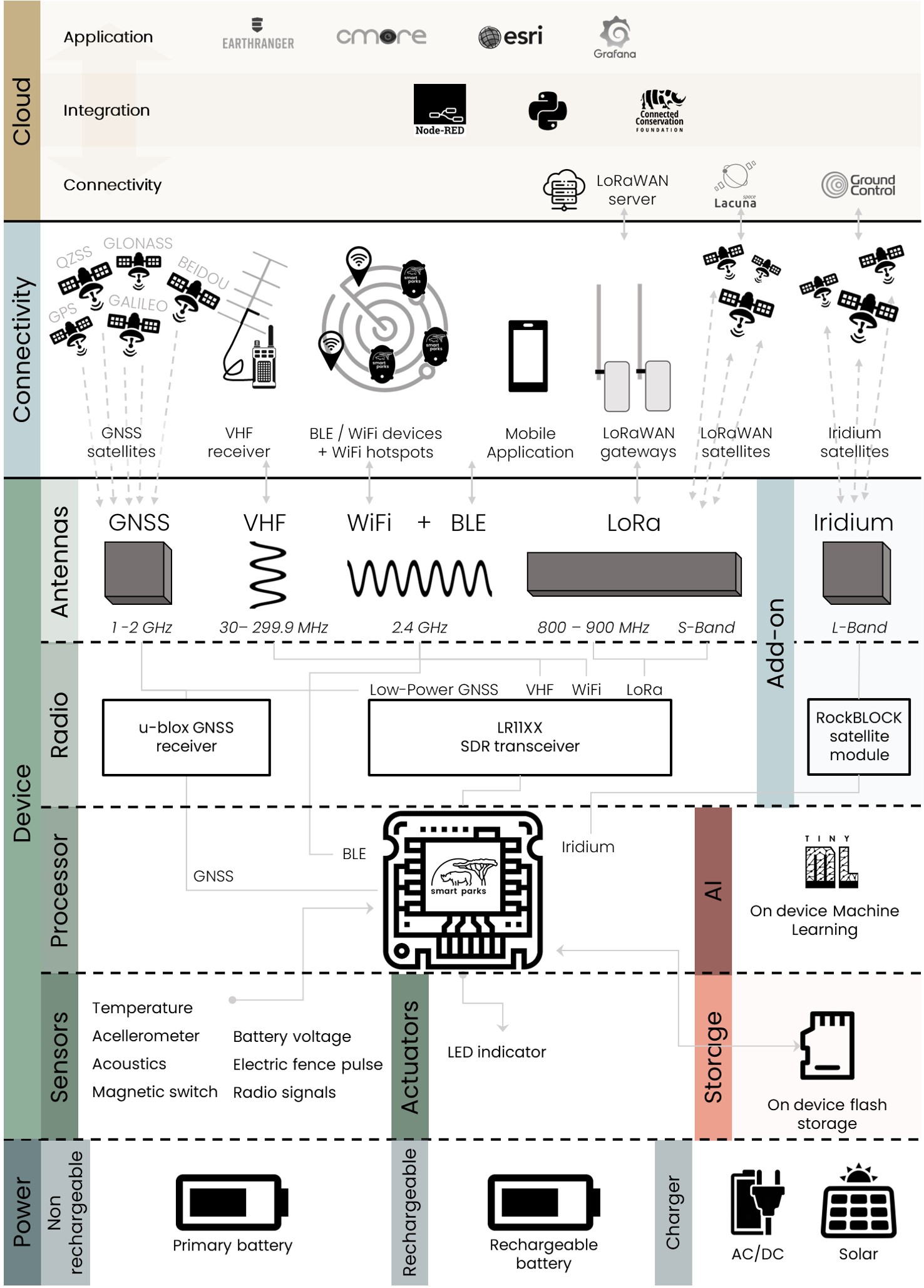
¶ Overview
¶ Ublox GNSS
All Edge devices have a Ublox GNSS chip for localization. We generally call this the “high power GPS” process, as all Edge devices can also use the LR11xx for GNSS localization using less power.
The Ublox process is has various settings to ensure it can be tuned to the specific application.
¶ Hot and cold fixes
The Ublox process works with “cold” and “hot” fixes, where cold fixes are used by the process to acquire almanac data need to perform reliable and fast hot fixes. Hot fixes are generally optimize for low power. The Ublox process always starts with cold fixes, until it has it's first successful fix. Only then it will continue with hot fixes.
The timeout and allowed retries for hot can cold fixes can be controlled.
¶ Ublox Intervals
The Ublox fix interval is controlled by the Ublox send interval. The device can also be set to use two intervals based on a 24 hour schedule.
¶ Resend last known position
A separate interval can be set to resent its last known position. This message will be send a Ublox GPS - short message.
¶ Backoff
Back off factor is defined with setting gps_backoff_factor with id 0x25. Value, divided by 10, represents the scaling factor between unsuccessful cold fix attempts. So for factor 1.5, setting 15 must be implemented, i.e.: [25 01 0F] to port 3. To disable backoff functionality, set value of coefficient to 1 (i.e. setting 10: [25 01 0A] command to port 3).
If two-interval operation is supported backoff will be reset on interval switch.
¶ Active tracking
In addition the Ublox process can be set in “Active Tracking” mode, where the Ublox chip is kept active in between the set ublox intervals.
To enable active tracking, user setting ublox_active_tracking with id 0x2B must me set to true. In this mode GPS module will be turned on all the time.
This will drastically increase power consumption of the device and generally should only be used on devises with rechargeable batteries and/or when connected to a permanent power source.
¶ Motion triggered GPS
Motion triggered GPS mode is supported. To enable the functionality, the user setting enable_motion_trig_gps with an id value of 0x2E must be enabled. Motion threshold is checked using the accelerometer sensor, the sensitivity of which can be configured by the motion_ths setting with an id value of 0x2D. Default value is set to 6 - refer to lis2dw12 sensor data-sheet for an in-depth explanation.
The motion triggered GPS fix functionality is split into two modes:
¶ 1. (DEFAULT) Skip GPS fix if no motion was detected during GPS fix interval
The device will skip the GPS fix if no movement was detected in the duration of a ublox_send_interval. If the device consecutively skips the gps fix for (user defined, default: 5) gps_skipped_triggered_interval times, the device will obtain a new fix and reset the internal skip-counter.
Setting the gps_skipped_triggered_interval to 0 will result in the device conducting a GPS fix on every ublox_send_interval.
¶ Example
enable_motion_trig_gps: true,
motion_ths: 6,
ublox_send_interval: 360 s,
gps_skipped_triggered_interval: 10If no motion is detected, the device will skip GPS fix acquisitions for ~3600s (approx. 10 * 360s) before performing a fresh fix. Detecting motion during one of the intervals will result in the device obtaining a fix and resetting the internal skip-counter.
¶ 2. Motion triggered GPS in specified time window
This motion trigger functionality can be used by itself and in congruence with other GPS features (except for #1 Skip GPS fix), as it does not rely on the standard ublox send/fix intervals.
Each motion trigger event temporarily increases the internal motion trigger counter for a (user defined, in seconds) gps_triggered_interval duration. When the internal trigger counter is equal or exceeds the (user configurable, default: 5) gps_motion_triggered_min_num_of_triggers_per_interval setting, a fresh GPS fix will be performed, independent of ublox fix/send intervals.
The minimum in-between fix failsafe duration applies (Hardset to 30s). The device will still count movement detections but a fix will not occur during the failsafe duration.
Setting gps_triggered_interval or gps_motion_triggered_min_num_of_triggers_per_interval to 0 will disable the feature and enable the #1 default GPS skip fix behavior.
¶ Example
enable_motion_trig_gps: true,
motion_ths: 6,
gps_triggered_interval:60 s,
gps_motion_triggered_min_num_of_triggers_per_interval: 5If at least 5 motion trigger events events are detected in a 60s period, a GPS fix will be performed.
¶ Resend position message
User can enable periodic resend of most recent valid position fix, by setting gps_resend_interval with id 0x0A that determines interval in seconds. A short GPS position message (port 13) will be send.
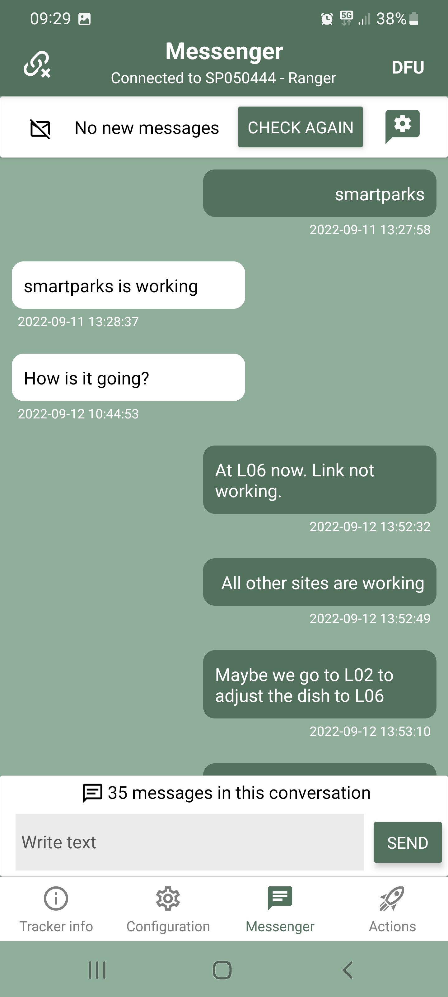
¶ Messaging
The Edge devices are able to send and receive small messages using the messaging feature.
- The number of unread messages is reported with value "n_mes" with id 0xEB.
- Messages are send and received on LoRaWAN port 28.
- “lr_messaging_retry_interval” with id 0x31 → default 60 seconds.
- “lr_messaging_retry_count” with id 0x32 → default 2 times.
Within the Smart Parks stack this features is used to send and receive messages in EarthRanger. For this to work there needs to be a proper integration between the LoRaWAN server and the EarthRanger messaging API.
¶ ShortRange advertisement
By default short range advertisement is enabled. To disable, set setting "ble_adv" with id 0x08 to false. Interval of the advertisement is governed by the "ble_advertisement_interval" setting with id 0x18 and with default value of 500 milliseconds.
When you disable the short range advertisement, you are no longer able to connect to the device over short range! So only do this when you have a stable and working LoRaWAN connection which allows to re-enable the advertisement if needed.
The device will advertise in the following format:
- Type: manufacturer data (0xFF) of length 16 bytes:
- byte 0-1: manufacturer data
0x0A61 - byte 2-15: status message
- byte 0-1: manufacturer data
- Type: data flags (0x01) of length 1
- Type: device name (0x09) of length 8 bytes
- Device name consist of "SP" and last 3 MAC address bytes, all in ascii format.
¶ PIN
Device can be protected with password that it set by "device_pin" setting with id 0x2A. It must be 4 bytes long. Only digits 0-9 are supported. If pin is set to: 0000 - default setting, pin is disabled. User can observe in the app if device is protected with pin, by looking for lock-key symbol, next to the device name.
Tracker needs to obtain pin 5 seconds after the connection is established, otherwise it will disconnect. If pin is forgotten or unknown, user can unlock the device with 16 bytes long AppKey.
¶ ShortRange scanning
Besides offering short range communication, the egde devices can perform scanning to detect other devices, including other Edge devices in particular.
The short range scanning modes or designed to work as a “contact tracing” application. For PAX (person) application, we still need to add this capability in the firmware.
The short range scan is controlled by the following settings:
- "ble_scan_interval" with id
0x1C→ interval in seconds for when the scan is performed and when finished stored and/or send.- default: 0 / OFF
- the results will be send on port 11.
- the results will only show a maximum of 20 BLE devices. This this has to do with the maximum payload size of each LoRaWAN message.
- "ble_scan_aggregated_interval" with id
0x1D→ interval in seconds for performing aggregating, storing and/or sending scan data.- default: 0 / OFF
- the results will be send on port 7.
- the results will only show the top 5 of the scanned BLE devices and the number of scanned BLE devices to a maximum of 20.
- "ble_scan_duration" with id
0x1B→ duration of the scan in milliseconds. Keep in mind it needs to be as least as long as the advertisement period of the target devices the device needs to detect.- default: 600 milliseconds
- "ble_scan_filter" with id
0x1E→ a filtering of scanned data can be implemented, before data is stored to flash or send. The following values of this setting are applicable:- 0 - no filter is implemented
- 1 - filter based on Smart Parks manufacturer ID (
0x0A61) - 2 - filter based on configured manufacturer ID set in “ble_scan_manufacturer_id”
- 3 - filter smartphones
- “ble_scan_manufacturer_id” with id
0x72→ when "ble_scan_filter" is set to 2, this setting can be used to filter on a specific manufacturer ID. - “ble_scan_report_zero_connections_found” with id
0x47→ a filter to ensure the device only reports when there are actually devices detected:- 0 - reporting continues even when no devices are detected
- 1 - reporting only continues when there is a minimum of 1 device detected during the last scan
To ensure the short range single scan and short range aggregated scan will be send and stored, ensure they are enabled in the “lr_send_flag" and “flash_store_flag”. With the App this can we done in the Configure data sending and storing section.
- "ble_advertisement_interval" with id
0x18→ duration of the advertisement in milliseconds. To ensure other Edge devices can see your Edge device, ensure this advertisement interval is below the scan duration. Otherwise it is more likely to not show up in the scan.- default: 500 milliseconds
Note: The device remains discoverable when it is performing a scan itself.
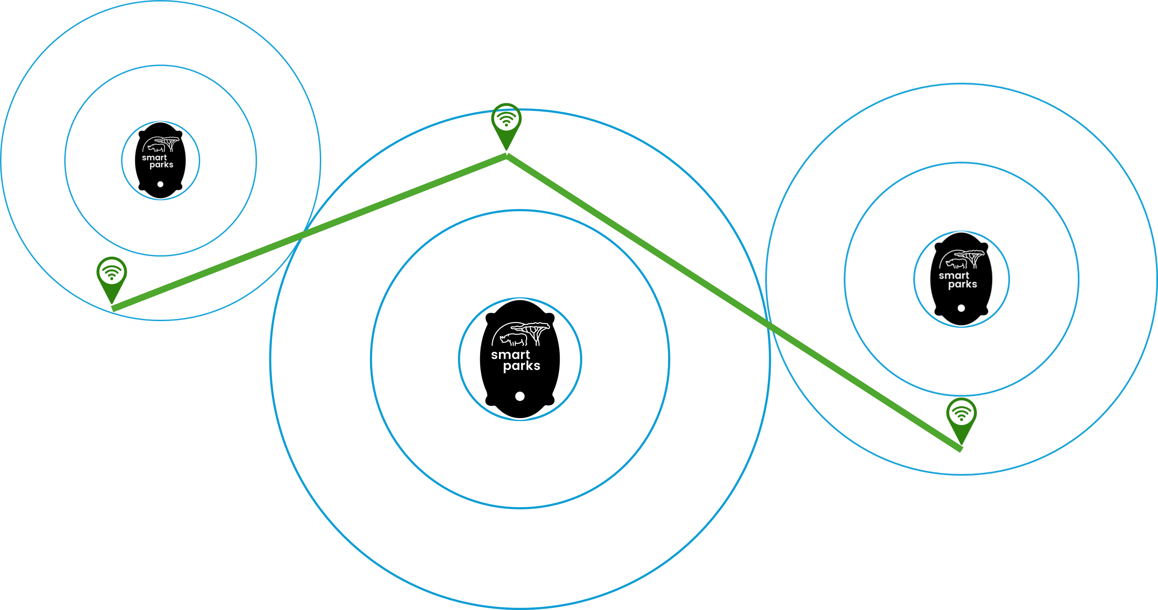
¶ Contact tracing
Using the short range scanning feature, the Edge devices can be used to allow for contact tracing. This feature needs a bit more explanation as it can be used in different ways.
- Static scanner, moving beacons → In this case, Edge devices placed at fixed locations, will regularly scan for specific beacons. This means that any beacon that comes in range of the Edge device that is scanning, will be reported. Because the location of the static scanners is known, it can be used as a localization tool, where the moving beacons can be simple, small and low power devices that do not have GNSS (GPS). An example use-case: Rabbits are fitted with simple <20 gram beacons and 50 RangerEdge devices are deployed in a grid throughout the landscape as static scanners. Now, every time one of the Rabbits comes in range (+/- 50 meter) of a RangerEdge, the approximate location of the Rabbit is known and will be transmitted to the Smart Parks system via the RangerEdge.
- Moving scanners, moving beacons → In this case, the Edge devices that scan for beacons are moving. This means the a moving scanner could be a CollarEdge device on wildlife, detecting another CollarEdge or a simple beacons attached to wildlife. The CollarEdge devices will now report whenever there is a contact with another CollarEdge or simple beacon. If the Edge device that is scanning also has GNSS (GPS) positioning enabled, this can also help to know where the contacts are taking place. An example use-case: Raccoons are fitted with CollarEdge devices, actively scanning for contacts with each other, to assist in the detection of possible disease transmission.
¶ WiFi scanning
Besides short range scanning, the egde devices can perform WiFi scanning to detect Wifi devices, including smartphones in particular.
The WiFi scan is performed by the LR11xx and has a fixed scanning duration.
The WiFi scan is controlled by the following settings:
- "wifi_scan_interval" with id
0x19→ interval in seconds for when the WiFi scan is performed and when finished stored and/or send.- default: 0 / OFF
- "wifi_scan_aggregated_interval" with id
0x1A→ interval in seconds for performing aggregating, storing and/or sending WiFi scan data.- default: 0 / OFF
To ensure the WiFi single scan and WiFi aggregated scan will be send and stored, ensure they are enabled in the “lr_send_flag" and “flash_store_flag”. With the App this can we done in the Configure data sending and storing section.
The WiFi scan settings are static and are currently define as:
- the scan is across all WiFi channels.
- the scan is using the type b scan.
- the scan is using the beacon and packet search mode (modes 3 - 5 are not supported in Modem-E)
- the scan has a limited number of max 12 scan results.
- the scan performs 2 retries per channel.
- the timeout in set to 110 milliseconds per channel.
Hence, the WiFi scan goes twice through 14 channels with max duration of 110 milliseconds per single channel scan, giving a maximum total scan duration time of 3080 milliseconds (+ 3 seconds).
¶ LR11xx LoRaWAN
Currently the following LoRaWAN Frequency plans are supported:
- EU868
- US915
- AU915
- WW2.4Ghz
- AS923 GRP1
- AS923 GRP2
- AS923 GRP3
- AS923 GRP4
- IN865
- KR920
- RU864
- CN470
- CN470 RP1.0
¶ LR11xx GNSS
The LR11xx module supports GNSS position data acquisition. The interval of when this position data is obtained is governed by the setting "lr_send_interval" with id 0x01. When this setting is set to 0, the LR11xx GNSS feature is disabled.
On each pre-defined "lr_send_interval" or when sending command "cmd_send_lr_fix" with id 0XAE, device will perform assisted GNSS scan, using latest obtained position and time, either provided by successful Ublox GPS fix or user input. To enable optimal LR GPS operation, provide latest device position and time via app when first starting to use it on a new location.
After the GNSS scan is performed, NAV message, containing scan status and position data will be send via LoRa to server to be resolved. More on the message structure can be found in subsection LR GPS Messages.
Error codes:
- Error code
0X07→ the device did not find any satellites during the GNSS scan. - Error code
0X08→ the Almanac is to old and needs updating.
¶ Almanac update
To successfully perform assisted GNSS scan, recent enough Almanac data needs to be provided. The almanac data is valid for up to 90 days. Latest Almanac age can be obtained with command get value, requesting value with id 0XEC. Almanac age is represented as uint16 value, nr. of days since last GPS 0 time i.e. since 7th April 2019.
If the GNSS scan results in an error 0X08, the Almanac is outdated and needs to be updated.
Due to its length, a full Almanac needs to be updated in several chunks. The total Almanac consists of 20 Bytes (Header) + 128 (number of SV) * 20 Bytes = 2580 Bytes. Using the command: "cmd_almanac_update" with id 0xB6, the user can provide parts of the Almanac data to the device either via LoRa or short range communication. The Smart Parks Connect App has a function to do all of the automatically.
Each command must be send to port 32 and must be of the form:
- byte 0: cmd id →
0xB6 - byte 1: length of the cmd
- byte 2-21: Almanac (id is obtained from first byte, as represents satellite id and 128 - header).
- ... stack as many as available
On received header with id 128, the firmware will perform Almanac update. The Update will take place only if provided date of the new Almanac is more recent than the already stored one.
¶ Satellite debugging data
To get more insight in the LR GPS performance, satellite data from latest scan can be obtained. Message "msg_lr_satellites" sent to port "port_lr_sat_data" contains satellite data, signal strength and other parameters. More on the message structure is written in the LR satellite data message section.
¶ Movement detection
For movement and orientation detection, we are using a 3-Axis accelerometer. We have been using the different accelerometers in different device hardware versions, however we are standardizing this currently to using only the LIS2DW12.
¶ Accelerometer
To get a better understand of how movement and motion is detected with an accelerometer, please check this Accelerometer Basics post from SparkFun:
¶ LIS2DW12
The LIS2DW12 has user-selectable full scales of ±2g/±4g/±8g/±16g and is capable of measuring accelerations with output data rates from 1.6 Hz to 1600 Hz.
We are using the follow low power settings:
- ±2g range
- power mode 0
- odr tof 12.5Hz
- threshold trigger with:
- threshold = <0x6>
- duration = <0x3>
Currently the Edge devices are taking a sample reading at each status interval and the firmware can set to trigger a Ublox GPS reading controlled by a motion threshold and a motion duration.
The status message (port 4) reports the accelerometer readings on the X, Y and Z axis.
- X → range: -20 and +20 m/s2
- Y → range: -20 and +20 m/s2
- Z → range: -20 and +20 m/s2
The interpretation of the X, Y and Z axis depends on the actual Edge device being used:
- RangerEdge
- RhinoEdge Cube
- RhinoEdge Puck 34
- RhinoEdge Puck 50
- <CollarEdge>
- WisentEdge
- ElephantEdge / ElephantFree
¶ Flash storage
The current Edge devices are all equipped with 32 megabit of Flash memory:
- 32.000.000 bits → 32 megabits
- 4.000.000 bytes → 4 megabytes
With the setting flash_storage_flag the user can control which messages will be stored in the flash memory.
The flash storage uses a FIFO (First-In-First-Out) principle. This means that once the memory is full, the oldest messages will be replaced by new messages.
We are in the process of upgrading Flash memory size per PCB. For RangerEdge PCB this is 256 megabit and for RhinoEdge PCBs this is 128 megabit.
¶ Example flash storage - GNSS positions
By default a port 2 - GPS location message is 32 bytes long. When we adding it to the flash storage, a timestamp and message ID is added, making the total size 37 bytes. This means we can store 4.000.000 / 37 = 108.108 port 2 - GPS location messages.
¶ Example flash storage - Status message
By default a port 4 - status message is 16 bytes long. When we adding it to the flash storage, a timestamp and message ID is added, making the total size 21 bytes. This means we can store 4.000.000 / 21 = 190.476 port 4 - status messages.
¶ Example flash storage - Real-Time BT-scan message
The size of real-time BT-scan message depends on the number of BT devices scanned by the process. This means a Real-Time BT-scan entry can be of maximum LoRaWAN payload size, which is 52 bytes. Adding the 5 additional bytes, the total port 11 message can take up to 57 bytes of storage. This means we can store 4.000.000 / 57 = 70.175 port 11 - Real-Time BT-scan messages (when all scans are using the maximum message size). The key here is to ensure the BT scan filters are optimized to what the device is intended to scan, so that flash storage and other communication traffic is minimized.
- If more BT devices are scanned then fit the maximum payload size, only the first payload will be send over LoRaWAN, but the additional payloads will be stored in flash. This means the storage space consumed per BT scan interval can be larger then a single LoRaWAN port 11 message.
¶ Acoustics
Some of our Edge devices are equipped with an acoustic sensor. We currently have not released any features based on this sensor, but our aim is open up many new use-cases. On of the best examples here is the use of acoustics on the ElephantEdge devices. This is inspired by the Elephant Listening Project.
¶ VM1010
- https://vespermems.com/products/vm1010/
¶ VM3011
- https://vespermems.com/products/vm3011/
¶ Magnetic switch
Most Edge devices have a magnetic switch to enable and disable the hibernation mode (sleep). This way the magnetic switch also serves as a reset/reboot function.
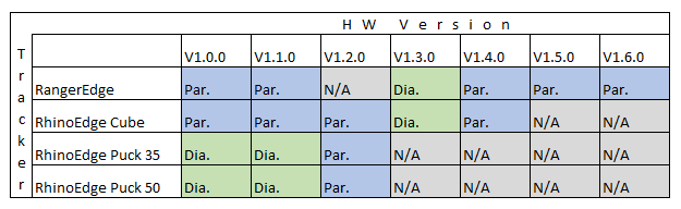
During various hardware revisions (version) we had to use different magnetic switch components, which has resulted in the inconvenient situation that some hardware versions require a different magnetic field orientation of the used magnet to function properly. In general we will aim to use axial (parallel to height) magnetized magnets. The following table can be used to identify what magnet works for your Edge device version:
- Par. → axial (parallel to height) magnetized magnets.
- Dia. → diametrically magnetized magnet.
¶ Hibernation mode
This feature is currently under review, so please do not use this feature on devices that can not be manually reset like CollarEdge and RhinoEdge.
The hibernation mode will:
- disable short range module → the device will no longer be visible in the Smart Parks Connect App.
- disable all operations like LoRa and GNSS
- disable flash - nothing new will be stored on the device
- disable all sensors (except magnetic switch)
To ensure the Edge device is put into hibernation mode the cmd_set_hibernation_mode command can be send:
- BLE:
32 195 0 - LoRaWAN:
Port 32- Hex:
C3 0 - Base64:
wwA=
The device can be activated again by triggering the magnetic switch with a magnet.
¶ Satellite communication
The Edge devices have build in support for adding a plug-and-play RockBLOCK satellite module. Once this module has been properly connected to the Edge device, the satellite feature should become available for configuration.
- Configure the Satellite feature on the Edge device.
- Register and activate the RockBLOCK satellite module through the RockBLOCK Managagement System.
¶ Enable / disable satellite feature
The Edge device advertises if the satellite functionality is currently enabled or disabled in the status in byte features (byte 15 if 0. and 1. byte are count as header), bit 1 (enabled/disabled). In the firmware, the satellite functionality is stored as the global sys_features.satellite_com and is set false on boot.
The user can enable or disable the satellite functionality by controlling the following setting:
"satellite_enabled": {
            "id": "0x3A",
            "enabled": true,
            "default": true,
            "min": false,
            "max": true,
            "length": 1,
            "conversion": "bool"
}The internal communication with the satellite module is done in the satellite_thread, which is created only if CONFIG_SATELLITE is selected.
¶ Sending messages via satellite module
Sending messages via the satellite module is governed similar to the LoRaWAN communication feature. The user can control which message type will be send via satellite using the following settings:
"sat_send_flag": {
            "id": "0x39",
            "enabled": true,
            "default": 138,
            "min": 0,
            "max": 4294967295,
            "length": 4,
            "conversion": "uint32"
},This setting determines if messages on port 1 to 32 will be send via satellite or not. If for a specific port the bit is set, the message type will be transferred to the satellite thread that indefinitely waits for a new command message to arrive. New messages are added to the satellite send buffer of maximum length 340 bytes. In a similar way to storing messages to the flash memory, the message is added to the buffer as:
- msg port number
- message
- timestamp
If there is not enough space in the buffer (340 bytes), the oldest message in the buffer is removed and the new message is added.
¶ Periodic sending of the satellite buffer
When set correctly, the satellite send buffer is send periodically. The internal communication thread checks if the satellite buffer needs to be send. The send interval is determined by the following setting:
"satellite_send_interval": {
            "id": "0x04",
            "enabled": true,
            "default": 3600,
            "min": 0,
            "max": 86400,
            "length": 4,
            "conversion": "uint32"
},If the satellite module is enabled and the interval is reached, the satellite module will try to send the buffer.
When the send command is received in the satellite thread, the device checks if the send buffer is empty or not. If the satellite send buffer is empty, a standard status message is added to the buffer. The satellite module then enters into sending mode by enabling the satellite module. The message is queued and the satellite send/receive loop is entered. The number of retries is defined by the following setting:
"satellite_retry": {
            "id": "0x3B",
            "enabled": true,
            "default": 10,
            "min": 1,
            "max": 15,
            "length": 1,
            "conversion": "uint8"
}A delay between retries is determined at random by the formula:
- 1-5 s for first 3 retries
- 5 - 20 s for first 6 retries
- 20 - 40 s for all the others
In the same send/receive loop, the module also tries to receive messages, that are parsed in the same way as other messages received via LR or BT.
The current number of retries is also reported in the device status message in byte 15.
¶ User command for sending satellite buffer
The user can initiate an immediate send of the satellite buffer by calling the command:
"cmd_send_sat_buffer": {
            "id": "0xC6",
            "length": 0,
            "conversion": "uint8",
            "value": 0
},¶ Fence monitoring
The Edge devices have build in support for adding a plu-and-play FenceEdge module. Once this module has been properly connected to the Edge device, the Fence monitoring feature should become available for configuration.
- Configure the Fence monitoring feature on the Edge device.
- Connect the Fence monitoring terminals to an electrified fence.
¶ Power supply
Edge devices have a primary power supply.
Do not confuse the primary power supply with the charging pins of the RangerEdge / FenceEdge. The charging pins can only be used in combination with selected rechargeable batteries.
RhinoEdge Cube: Min - 2.8V, Max - 5,5V. Battery measurement will max out at 4.3V
RhinoEdge Puck 34: Min - 2.8V, Max - 5,5V. Battery measurement will max out at 4.3V
RhinoEdge Puck 50: Min - 2.8V, Max - 5,5V. Battery measurement will max out at 4.3V
CollarEdge: Min - 2.8V, Max - 5.5V. Battery measurement will max out at 4.3V
RangerEdge: Min - 2.8V, Max - 5.5V. Battery measurement will max out at 4.,3V
FenceEdge: Min - 2.8V, Max - 5.5V. Battery measurement will max out at 4.3V
WisentEdge: Min - 2.8V, Max - 5.5V. Battery measurement will max out at 4.3V
ElephantEdge: Min - 2.8V, Max - 5.5V. Battery measurement will max out at 4.3V
ElephantFree: Min - 2.8V, Max - 5.5V. Battery measurement will max out at 4.3V
¶ S-Band Satellite LoRaWAN
This feature is currently in experimental state. Please report bugs to the Smart Parks team.
From RangerEdge Hardware version 1.7 and Firmware version 6.0 there is support for LoRaWAN over S-band to satellite. We are testing with the following satellite, supported by Lacuna Space and Omnispace using the following satellite:
The current test setup is using The Things Network as the LoRaWAN server for delivering the LoRaWAN payloads.
¶ How to send a S-Band LoRaWAN uplink
Currently there is no user friendly interface available in the Smart Parks Connect App to control this feature. This will be added soon. For now you can use Actions > Management > Write custom command to control this feature.
Send regular S-Band LoRaWAN uplink:
- Every 5 minutes:
3 32 4 44 1 0 0 - Turn off:
3 32 4 0 0 0 0
Send single S-Band LoRaWAN uplink:
32 189 0
Keep in mind that the Smart Parks Connect App will disconnect from the RangerEdge whenever the device tries to send the S-Band LoRaWAN uplink. This is to prevent any signal disruption. You will be able to reconnect the Smart Parks Connect App to the device once the S-Band LoRaWAN uplink has been send.
The S-Band LoRaWAN uplink consists of a Status message (port 4) and a Last known position message (port 13). If the GPS of the device is turned OFF and there is no last known positions stored in the device yet, there will be no GPS information in the S-Band LoRaWANu uplink message. Please ensure the GPS interval is enabled when you want to see (recent) GPS updates.
To ensure the device does not run out of power unexpectedly, please turn OFF the S-Band LoRaWAN uplink interval after testing and if needed, also turn OFF the GPS interval if enabled.
¶ Provisioning S-Band LoRaWAN
The LoRaWAN S-Band uses a separate provisioning then the terrestrial LoRaWAN. Provisioning of the LoRaWAN S-Band is done via the following settings:
s_band_app_key-0x44- 16 byte array containing AppSKey for correct message encoding.s_band_network_key-0x45- 16 byte array containing NwkSKey for correct message encoding.s_band_dev_adr-0x46- 4 byte array containing Device address for correct message encoding.
All test devices have been provisioned with the correct credentials already.
¶ Regular LoRaWAN messages
The current firmware uses a separate LoRaWAN provisioning for the terrestrial traffic, which is configured through the regular steps in this Wiki. Note that the regular LoRaWAN messages will not show up in the same LoRaWAN application as the S-Band LoRaWAN messages.
¶ Cardiac Monitoring Device
Edge devices running firmware +v6 have support for specific Cardiac Monitoring Devices called Q (CMDQ) using the BT protocol.
¶ CMDQ feature settings
The following settings are to control the CMDQ feature.
Enable/Disable CMDQ:
"cmdq_enabled": {
	"id": "0x49",
	"default": true,
	"min": false,
	"max": true,
	"length": 1,
	"conversion": "bool"
}CMDQ scan duration:
"cmdq_scan_duration": {
	"id": "0x4A",
	"default": 10000,
	"min": 1,
	"max": 10000,
	"length": 4,
	"conversion": "uint32"
}CMDQ search interval:
"cmdq_search_interval": {
	"id": "0x4B",
	"default": 180,
	"min": 1,
	"max": 10000,
	"length": 4,
	"conversion": "uint32"
}CMDQ wait duration:
"cmdq_on_no_detection_wait_duration": {
	"id": "0x4C",
	"default": 1800,
	"min": 1,
	"max": 10000,
	"length": 4,
	"conversion": "uint32"
}CMDQ mac:
"cmdq_searched_mac_address": {
	"id": "0x4D",
	"default": "{0xD8,0x10,0x68,0xAC,0xDA,0xE4}",
	"min": "{0x00,0x00,0x00,0x00,0x00,0x00}",
	"max": "{0x00,0x00,0x00,0x00,0x00,0x00}",
	"length": 6,
	"conversion": "byte_array"
}CMDQ reporting interval:
"cmdq_reporting_interval": {
	"id": "0x4E",
	"default": 30,
	"min": 1,
	"max": 10000,
	"length": 4,
	"conversion": "uint32"
}¶ Open Sky detection
Edge devices running firmware +v6 have support for Open Sky detection.
This feature is currently in BETA, which means it is only used in specific projects.
¶ Open Sky detection feature settings
The following settings are to control the Open Sky detection feature.
¶ Periodic scanning
¶ Multiple interval periodic open sky detection scanning
If rf_open_sky_detection_multiple_intervals is set to true, the device will use two intervals, effectively splitting the day into two. The starting hour of each interval can be controlled by rf_open_sky_detection_interval1_start and rf_open_sky_detection_interval2_start respectively. In the same manner as specified above for the rf_open_sky_detection_interval1, the second scanning interval can be controlled by setting rf_open_sky_detection_interval2. Checkout the notes and examples below the setting definitions.
Note: If both
interval*_starttimes are set to the same value,interval1is selected.
Open Sky detection Enable/Disable:
"rf_open_sky_detection_enabled": {
    "id": "0x58",
    "default": true,
    "min": false,
    "max": true,
    "length": 1,
    "conversion": "bool"
}Open Sky detection Interval1 in seconds:
"rf_open_sky_detection_interval1": {
    "id": "0x59",
    "default": 120,
    "min": 0,
    "max": 86400,
    "length": 4,
    "conversion": "uint32"
}Open Sky detection multiple intervals:
"rf_open_sky_detection_multiple_intervals": {
    "id": "0x5B",
    "default": true,
    "min": false,
    "max": true,
    "length": 1,
    "conversion": "bool"
}Open Sky detection Interval1 start time:
"rf_open_sky_detection_interval1_start": {
    "id": "0x5C",
    "default": 7,
    "min": 0,
    "max": 23,
    "length": 1,
    "conversion": "uint8"
}Open Sky detection Interval2 start time:
"rf_open_sky_detection_interval2_start": {
    "id": "0x5D",
    "default": 19,
    "min": 0,
    "max": 23,
    "length": 1,
    "conversion": "uint8"
}Open Sky detection Interval2:
"rf_open_sky_detection_interval2": {
    "id": "0x5E",
    "default": 60,
    "min": 0,
    "max": 86400,
    "length": 4,
    "conversion": "uint32"
}Examples of multiple interval use:
1. Scan once each hour during interval1. Scan every half hour during interval2.
"rf_open_sky_detection_enabled": true
"rf_open_sky_detection_multiple_intervals": true
"rf_open_sky_detection_interval1_start": 13
"rf_open_sky_detection_interval2_start": 18
"rf_open_sky_detection_interval1": 3600
"rf_open_sky_detection_interval2": 18002. Scan once each hour only during daytime. Don't scan during nighttime.
"rf_open_sky_detection_enabled": true
"rf_open_sky_detection_multiple_intervals": true
"rf_open_sky_detection_interval1_start": 7
"rf_open_sky_detection_interval2_start": 18
"rf_open_sky_detection_interval1": 3600
"rf_open_sky_detection_interval2": 0¶ Scanning duration
Control the scanning duration by changing the setting:
"rf_open_sky_detection_duration": {
    "id": "0x5A",
    "enabled": true,
    "default": 60,
    "min": 0,
    "max": 86400,
    "length": 4,
    "conversion": "uint32"
}¶ Open sky detection prior to GPS fix
Setting the gps_open_sky_detection_bitmask bit 0 will result in the device performing a RF open sky detection scan prior to conducting a GPS fix.
¶ Bitmask
Bitmask: Most significant bit is used to check if the band selection feature is enabled. Each following bit corresponds to a band on which the scan will be performed. Setting the bit will include the corresponding band in the scan.
| Bit # | Description |
|---|---|
| Bit 7 | Enabled? [True - False] |
| Bit 6 | [100 - 200] MHz |
| Bit 5 | [400 - 500] MHz |
| Bit 4 | [800 - 1000] MHz |
| Bit 3 | [1200 - 1400] MHz |
| Bit 2 | [1500 - 1600] MHz |
| Bit 1 | [1800 - 2100] MHz |
| Bit 0 | [2400 - 2500] MHz |
Note: Bitmask bit 0 represents the least significant bit.
"gps_open_sky_detection_bitmask": {
    "id": "0x6F",
    "default": 0,
    "min": 0,
    "max": 255,
    "length": 1,
    "conversion": "uint8"
}¶ Average RSSI threshold
The average detected RSSI value from the conducted open sky detection scan is compared to the set threshold. If both Average RSSI and Max RSSI values exceed their respective thresholds, the device will perform a GPS fix.
"gps_open_sky_detection_avg_rssi_threshold_dbm": {
    "id": "0x70",
    "default": -70,
    "min": -128,
    "max": 0,
    "length": 1,
    "conversion": "int8"
}¶ Max RSSI threshold
The max detected RSSI value from the conducted open sky detection scan is compared to the set threshold. If both Average RSSI and Max RSSI values exceed their respective thresholds, the device will perform a GPS fix.
"gps_open_sky_detection_max_rssi_threshold_dbm": {
    "id": "0x71",
    "default": -50,
    "min": -128,
    "max": 0,
    "length": 1,
    "conversion": "int8"
}¶ RF bands used for scanning
- band 0:
100 - 200 Mhz - band 1:
400 - 500 Mhz - band 2:
800 - 1000 Mhz - band 3:
1200 - 1400 Mhz - band 4:
1500 - 1600 Mhz - band 5:
1800 - 2100 Mhz - band 6:
2400 - 2500 Mhz
¶ VHF
VHF (Very High Frequency) transmission beacon.
Edge devices running firmware above version v6 have support for VHF.
On set interval, the feature will add a VHF transmission event to the LR queue.
Only one VHF event can exist inside the LR queue at a time, to avoid overfilling the queue. Processing other device features (GPS fix, LoRaWAN message transmission, RF scanning, Open Sky detection, s-band, etc.) affects the VHF pulse interval consistency. Depending on enabled features and their respective settings, the interval could be delayed from a few seconds to a few minutes.
¶ General operational settings
¶ vhf_enabled 0x61
"vhf_enabled": {
    "id": "0x61",
    "default": false,
    "min": false,
    "max": true,
    "length": 1,
    "conversion": "bool"
}¶ vhf_num_of_packets_per_burst 0x67
Set the default number of VHF "beeps" per burst
"vhf_num_of_packets_per_burst": {
    "id": "0x67",
    "default": 1,
    "min": 1,
    "max": 255,
    "length": 1,
    "conversion": "uint8"
}¶ vhf_time_between_packets_ms 0x68
Set the default time in between VHF "beeps" per single burst. Only applicable when more than one packet is sent per burst.
"vhf_time_between_packets_ms": {
    "id": "0x68",
    "default": 250,
    "min": 1,
    "max": 10000,
    "length": 2,
    "conversion": "uint16"
}¶ vhf_external_path 0x69
By default, VHF transmission is done using the on-board LoRaWAN antenna. Enabling the external path, the board will send the VHF transmission over the external VHF antenna connector.
This setting is applicable only for non-rhino* boards as rhino* boards do not have the appropriate VHF connector. Enabling this setting while using a rhino* board will produce no change in operation.
Affected Rhino* board types:
- RhinoEdge Cube
- RhinoEdge Puck 35
- RhinoEdge Puck 50
The external path can be set using the following setting:
"vhf_external_path": {
    "id": "0x69",
    "default": false,
    "min": false,
    "max": true,
    "length": 1,
    "conversion": "bool"
}¶ vhf_tx_frequency_khz 0x6A
Command example: Set the VHF transmission frequency to 150000: 0x6A 0x04 0xF0 0x49 0x02 0x00 send to port 3.
"vhf_tx_frequency_khz": {
    "id": "0x6A",
    "default": 150000,
    "min": 150000,
    "max": 300000,
    "length": 4,
    "conversion": "uint32"
}¶ vhf_single_pulse_duration_ms 0x6B
Sets the duration of each pulse inside of a burst.
"vhf_single_pulse_duration_ms": {
    "id": "0x6B",
    "default": 20,
    "min": 5,
    "max": 10000,
    "length": 2,
    "conversion": "uint16"
}¶ Two intervals operation
VHF scheduling allows for two separate intervals
Two-interval operation is supported. To use 2 intervals functionality, setting: vhf_multiple_intervals with id: 0x66 must be turned on with command: 66 01 00 send to port 3.
We can divide each day into two intervals: interval1 and interval2. The start of each interval is defined by vhf_interval1_start and vhf_interval2_start respectively. Supported values are from 0 to 23, representing UTC time hours. Using these settings, the intervals are defined as: interval1: [vhf_interval1_start, vhf_interval2_start) and interval2: [vhf_interval2_start, vhf_interval1_start).
Setting both intervals to the same hour will result in the selection of
interval1.Setting
interval1orinterval2to 0 will turn off the feature for that interval respectively.
¶ Example
vhf_interval1: 15 minvhf_interval2: 1 hvhf_interval1_start: 7vhf_interval2_start: 18
This means that at 07:00 UTC, the device will produce a VHF burst every 15 minutes. When we switch to interval2 at 18:00 a VHF burst will be transmitted every hour until the next day at 7.00 when we switch back to interval1.
Start of interval1 can be changed with command: 64 01 val_in_hex_format send on port 3.
¶ vhf_interval1 0x62
"vhf_interval1": {
    "id": "0x62",
    "default": 60,
    "min": 0,
    "max": 86400,
    "length": 4,
    "conversion": "uint32"
}¶ vhf_interval1_start 0x64
"vhf_interval1_start": {
    "id": "0x64",
    "default": 7,
    "min": 0,
    "max": 23,
    "length": 1,
    "conversion": "uint8"
}¶ vhf_multiple_intervals 0x66
"vhf_multiple_intervals": {
    "id": "0x66",
    "default": false,
    "min": false,
    "max": true,
    "length": 1,
    "conversion": "bool"
}¶ vhf_interval2 0x63
"vhf_interval2": {
    "id": "0x63",
    "default": 60,
    "min": 0,
    "max": 86400,
    "length": 4,
    "conversion": "uint32"
}¶ vhf_interval2_start 0x65
"vhf_interval2_start": {
    "id": "0x65",
    "default": 19,
    "min": 0,
    "max": 23,
    "length": 1,
    "conversion": "uint8"
}¶ Drop-off
CollarEdge devices has a specific port used for the decoupling / releasing of the collar. On command the device turns on power to the (P3) connector for 5 seconds.
This feature is currently in BETA, which means it is only used in specific projects.
The following command will trigger the drop-off function: 0xCD 0x00
¶ Outdoor detection
For Pangolin monitoring in Namibia, we have designed a firmware feature that tries to detect if the Pangolin is in his burrow (indoor) or outside. This way we can ensure the GNSS (GPS) location functions is only activated when being outside. This should increase the chances of having successful location fixes and a reduce power consumption. The implemented functions is based on data collected from Pangolin wearing our PangolinEdge devices.
The Outdoor detection module is designed to detect when the device is outside based on the gathered accelerometer, temperature, and temporal data. That data is then compared with expert-provided weights from which the device can approximate the probability that it is outside.
¶ Basic operation
This module is currently used to control GPS fixes. Currently, the only available expert-provided weights are for Pangolins.
¶ Configuration
The module currently operates with 3 user-configurable settings:
"outdoor_detection_enabled": {
    "id": "0x7A",
    "default": false,
    "min": false,
    "max": true,
    "length": 1,
    "conversion": "bool"
},
"outdoor_detection_tau": {
    "id": "0x7B",
    "default": 11,
    "min": 0,
    "max": 100,
    "length": 1,
    "conversion": "uint8"
},
"outdoor_detection_parameters": {
    "id": "0x7C",
    "default": "{0xCB,0xEC,0x6B,0x12,0x2A,0x13,0x79,0x0F,0x20,0x1C,0x00,0x00}",
    "min": "{0x00,0x00,0x00,0x00,0x00,0x00,0x00,0x00,0x00,0x00,0x00,0x00}",
    "max": "{0x00,0x00,0x00,0x00,0x00,0x00,0x00,0x00,0x00,0x00,0x00,0x00}",
    "length": 12,
    "conversion": "byte_array"
}Setting the outdoor_detection_enabled to true enables this module and disables the classically used GPS fix interval.
The outdoor_detection_tau user settings controls the probability needed for the module to trigger a GPS fix.
The outdoor_detection_parameters are used to fine-tune the weights responsible for calculating the final outdoor probability. The Parameters are set as follows:
- Bias (2 bytes)
- Temperature weight (2 bytes)
- Accelerometer weight (2 bytes)
- Hour weight (2 bytes)
- Time-zone offset in seconds (4 bytes) - Default offset is set to Central Africa time (GMT+2)
Important
All weights need to be little endian encoded integers! All values should be multiplied by 1000 prior to saving.
¶ Configuration example
Lets set the outdoor detection parameters to the below specified values:
| Parameter | Value | Value * 1000 | Hex (little endian) | Byte position |
|---|---|---|---|---|
| Bias | -4.917 | -4917 | {0xCB,0xEC} | 0 - 1 |
| Temperature weight | 4.715 | 4715 | {0x6B, 0x12} | 2 - 3 |
| Accelerometer weight | 4.906 | 4906 | {0x2A, 0x13} | 4 - 5 |
| Hour weight | 3.961 | 3961 | {0x79,0x0F} | 6 - 7 |
| Time-zone offset (s) | 7200 | 7200 | {0x20, 0x1C} | 8 - 11 |
¶ Switch
The RangerEdge devices now have a generic switch feature that allows to use the fence connector as an interface for various switching features.
This module describes a general purpose external switch detection feature, which allows the user to connect any compatible sensor, sensor board, or simple switch.
Pin Definition
| # | Pin (Schematic) | On-Board abbreviation | General pin description | External SWITCH pin usage description |
|---|---|---|---|---|
| 1 | GND |
GND |
Ground | Ground |
| 2 | 2.8V power |
2.8V |
2.8 Volt power supply | 2.8 Volt power supply |
| 3 | GPIO |
GPIO |
General purpose input - output pin | GPIO output - Used for enabling external switch |
| 4 | AIN/GPIO |
AN |
Analog input / General purpose IO pin | GPIO - input signal line |
Pins
The GPIO output pin (#3) is enabled at feature initialization, set to high, can be used to enable the external switch if needed.
When using the external switch feature, the AN pin is configured into a GPIO pin, so the voltage considered LOW or HIGH are voltages the nrf52 chip considers low and high values:
Digital input thresholds (VDD = supply voltage)
Logical LOW (0) V_IN ≤ 0.3 × VDD
Logical HIGH (1) V_IN ≥ 0.7 × VDD
Undefined / indeterminate Between 0.3 × VDD and 0.7 × VDD
Activity detection
Activity detection will send a detection message immediately after activity is detected. After activity was detected, as soon as inactivity is detected the device will send a message signaling that activity has ended. The message will contain a activity value of 0 and a duration_ms value with the total activity duration.
State changed message content (Port 19)
| Payload byte # | Description |
|---|---|
| 0 | Message id. |
| 1 | Message length |
| 2 | Activity detected (True/False) |
| 3 - 6 | Activity / Inactivity duration in milliseconds |
Status message content (Port 20)
On every report period, a status message is sent to port 20
| Payload byte # | Description |
|---|---|
| 0 | Message id. |
| 1 | Message length |
| 2 | Activity detected (True/False) |
| 3 - 6 | Number of state changes to ACTIVE detected |
¶ Impulse counter
When sending a status report over LoRa, the impulse counter will set the activity indicator byte to 2, signaling the message is a impulse counter message.
Status message content (Port 20)
| Payload byte # | Description |
|---|---|
| 0 | Message id |
| 1 | Message length |
| 2 | 2 signaling a impulse counter message |
| 3 - 6 | Number of detected impulses |
¶ User Settings
External SWITCH detection uses the following user settings:
¶ external_switch_detection_enabled
Turns on external switch detection.
This setting must not be enabled concurrently with the
fence_enabled! If both are enabled, the firmware will automatically disable the external switch functionality.
"external_switch_detection_enabled": {
    "id": "0x7E",
    "default": false,
    "min": false,
    "max": true,
    "length": 1,
    "conversion": "bool"
}¶ external_switch_detection_trigger_type
Trigger type controls the way in which the device will interpret the input line signal (AN - GPIO input line).
Available settings:
| # | Description |
|---|---|
| 0 | The device will interpret a logical 0 on the AN (GPIO input) pin as a sign of activity |
| 1 | The device will interpret a logical 1 on the AN (GPIO input) pin as a sign of activity (Default) |
"external_switch_detection_trigger_type": {
    "id": "0x7F",
    "default": 1,
    "min": 0,
    "max": 1,
    "length": 1,
    "conversion": "uint8"
}¶ external_switch_detection_trigger_debounce_ms
Debouncing controls how many milliseconds after detecting the AN (GPIO input) line changing state the device ignores additional input state changes.
Activity detection specific After the debouncing period expires, the device will read the state of the
AN(GPIO input) line again, confirming that the state is correctly set. This is done to fix the issue where the input line changed state prior to the debouncing duration expiring, resulting in the device reporting activity incorrectly.
Setting debouncing to 0 will turn
OFFthe debouncing logic, which can slow down the device and potentially make it unusable, if the input GPIO pin is floating or in a pull mismatch.
"external_switch_detection_trigger_debounce_ms": {
    "id": "0x80",
    "default": 50,
    "min": 0,
    "max": 2000,
    "length": 2,
    "conversion": "uint16"
}¶ external_switch_detection_reporting_interval
Reporting interval at which a report is sent over LoRa. Setting the interval to 0 will disable it.
Activity detection specific:
This setting only controls the periodic status reporting. When activity was detected after a period of inactivity (or when going from a period of activity to inactivity), the device will instantly send a message over LoRa, even if the reporting interval is set to 0.
"external_switch_detection_reporting_interval": {
    "id": "0x81",
    "default": 0,
    "min": 0,
    "max": 86400,
    "length": 4,
    "conversion": "uint32"
}¶ external_switch_send_inactivity_report
Enabling this setting will allow the device to send report of inactivity when external_switch_detection_reporting_interval expires.
"external_switch_send_inactivity_report": {
    "id": "0x82",
    "default": true,
    "min": false,
    "max": true,
    "length": 1,
    "conversion": "bool"
}¶ external_switch_minimal_report_duration_ms
To avoid filling up the LoRa queue with detections that slip past the debouncing period, this setting allows users to select a minimal duration the external switch needs to detect activity before sending a report over LoRa.
"external_switch_minimal_report_duration_ms": {
    "id": "0x83",
    "default": 250,
    "min": 0,
    "max": 65000,
    "length": 2,
    "conversion": "uint16"
}¶ external_switch_input_pull
Set this pull of the AN (GPIO input) line for more accurate activity and counting measurements.
| # | Description |
|---|---|
| 0 | No pull |
| 1 | Pull Up |
| 2 | Pull Down |
If your external switch already adds pull to the input line, setting this setting incorrectly could result in increased power consumption and other undefined behavior.
"external_switch_input_pull": {
    "id": "0x84",
    "default": 0,
    "min": 0,
    "max": 2,
    "length": 1,
    "conversion": "uint8"
}¶ external_switch_counter_enabled
Toggle between switch activity detection and impulse counter.
Enabling this setting will change the external switch detection behavior from activity detection to impulse counting. The device will (based on external_switch_detection_trigger_type) count the number of detected state changes to activity. The device counts how many times the state changed from a state of inactivity to activity (ignoring state changes inside of the debounce interval) inside of the reporting interval external_switch_detection_reporting_interval.
"external_switch_counter_enabled": {
    "id": "0x85",
    "default": false,
    "min": false,
    "max": true,
    "length": 1,
    "conversion": "bool"
}