¶ RhinoEdge Puck 34 Deployment
Tests with the RhinoEdge tracking devices have shown that rhino horn material blocks the GPS signal significantly. This means even with perfect antenna tuning, getting low power results from any GPS sensor inside a rhino horn is extremely difficult. However, with the adequate tuning and specific placement of each type of RhinoEdge tracker, a stable performance can be accomplished.
We conclude that the less horn material is between the GPS antenna and the satellites in the sky, the better the GPS performance. Therefore, we strongly advice and promote the top-loading method, as this method outperforms the side-loading method. The RhinoEdge Cube and RhinoEdge Puck 34 are designed for the top-loading method. We strongly advice against using the side-loading method with these devices. The RhinoEdge Puck 50 can be deployed using the top-loading and side-loading method, as the antenna surface of this device is significantly larger than the Cube and Puck 34.
For all tracker methods, the exact placement is critical in order to safeguard the performance of the RhinoEdge devices. Therefore, the deployment of the devices should be performed according to the prescribed methods in this document to get a positive result. These methods include the use of specific tools and filament materials.
¶ Specifications
- Dimensions:
- Diameter: 33 mm
- Height: 36 mm
- Weight: 41 grams
- Internal LoRaWAN antenna
- Internal linear GNSS antenna – tuned to this exact deployment method!
- 3 batteries – 3600mAh
- High-power GPS: This device has three small batteries, therefore the high-power GPS can be used on a higher interval than the RhinoEdge Cube. With a 2 hour GPS interval, an average time-to-fix of 50 seconds and a status message interval of 60 minutes, the estimated lifespan of the device is 2 years.
- Low-power GPS: The performance of the low-power GPS is not stable. In some cases the low-power GPS performs, in other cases it does not resolve any GPS locations. Therefore, we advise against using the low-power GPS method as the main method for acquiring location data. Further long-term usage in the field will give us insight on the performance and reliability.
¶ Method: top-loading
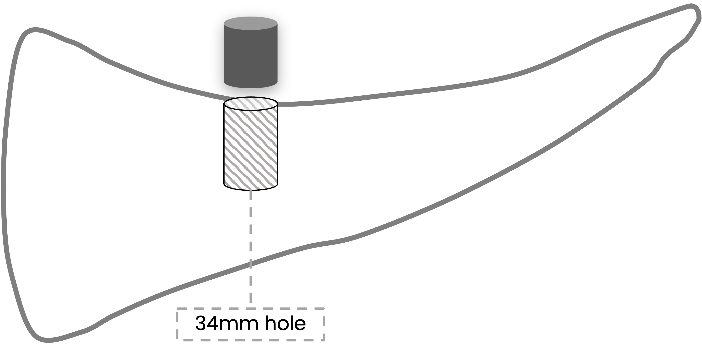
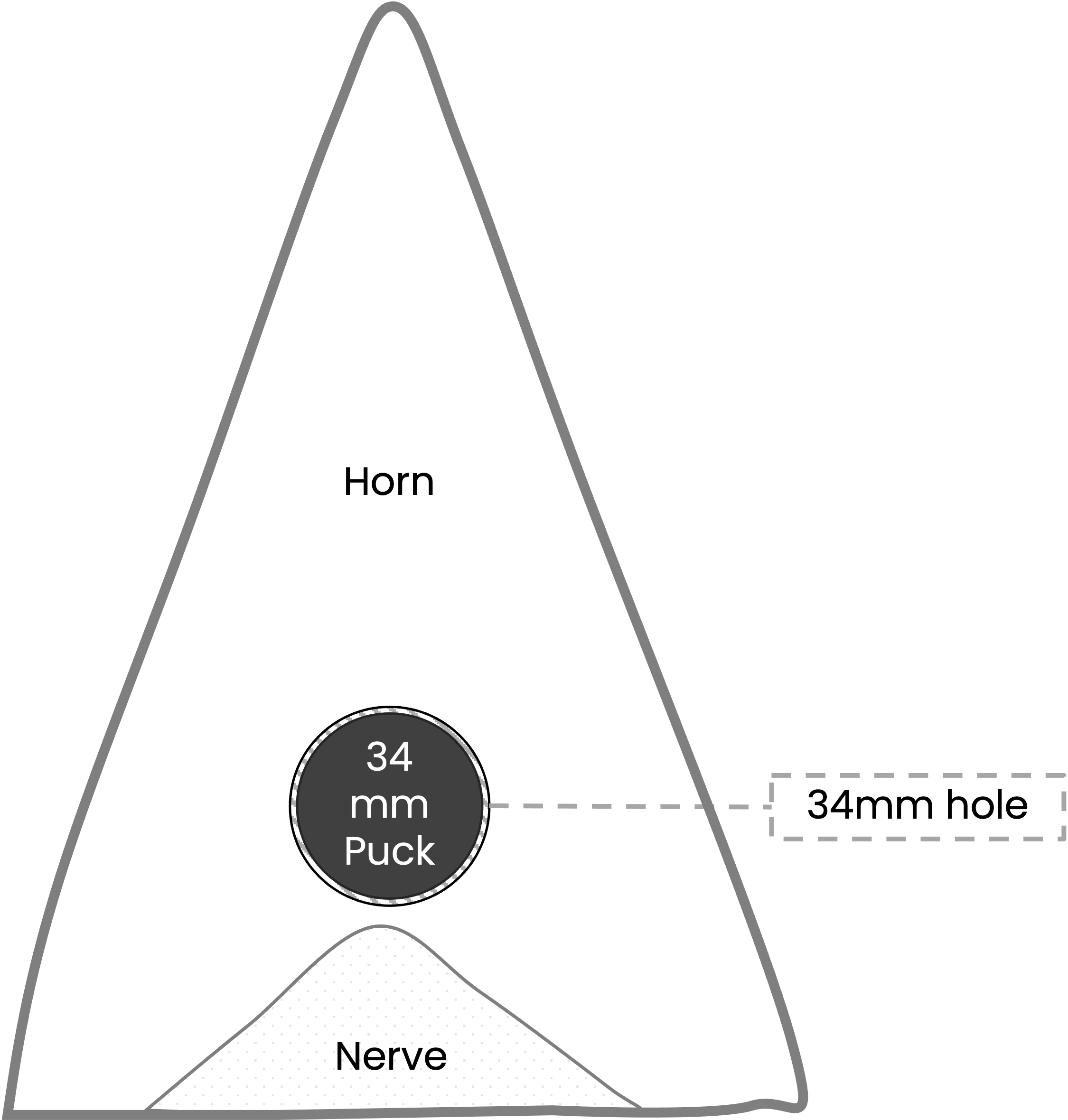
This device is performing good using the top-loading method, using a Forstner bit 34 mm. The RhinoEdge Puck 34 is inserted into the 34 mm hole from the top surface of the inside curve of the horn. The RhinoEdge Puck 34 has an internal LoRaWAN antenna, therefore no additional hole needs to be drilled.
¶ Illustrations


¶ Settings
¶ Pre-deployment
¶ Device check
- Ensure the device has the latest device firmware - use the Smart Parks Connect app to check this.
- Ensure the device has the correct settings - use the Smart Parks Connect app to check this.
- If you are using a unique PIN to connect to the device, please make sure you have this with you.
- Ensure the device does not report any critical errors - use the Smart Parks Connect app to check this.
- Ensure the device is JOINED to the LoRaWAN network and is sending messages like expected.
- Check this with scanning the device using the Smart Parks Connect app and look for a JOIN error.
- Check the messages from this device in your LoRaWAN server.
- TIP: do all these checks <24 hours before each deployment, so that you have time to take action if issues occur.
¶ Deployment tools check
- Ensure you have all the needed deployment tools:
- Vettec Adhere 47150
- Vettec mixt tips
- Vettec Applicator
- Forstner bit 34mm
- Android smartphone with the Smart Parks Connect app
- TIP 1: permanent marker
- TIP 2: ruler
- TIP 3: painters tape
¶ Deployment
- Mark the location to drill the 34mm hole
- Drill the 34 mm hole
- Go +/- 46 mm deep → going deeper will reduce the GNSS signal strength, because the signals have to travel trough more rhino horn material and Vettec Adhere.
- Create a cavity inside the hole → this will ensure the Vettec Adhere can not escape the hole when solidified.
- Put the RhinoEdge Puck 34 inside the hole
- Make sure the GNSS antenna (flat surface of the device) is pointing towards the opening the of 34 mm hole → Vettec Adhere is less blocking to GNSS signals then the rhino horn material.
- Apply the Vettec Adhere
- Start with pouring a little bit of Vettec Adhere on the bottom of the 34 mm hole.
- Push in the RhinoEdge Puck 34 and start filling up the 34mm hole by pressing the mix tip as deep in as possible → pressing the mix tip inside the hole while pouring in the Vettec Adhere will ensure air bubbels are pushed out.
- NOTE: the Vettec Adhere has a very fast set time of 30 seconds → once you start applying Vettec Adhere you need to commit to ensure there are no air bubbels
- NOTE: the Vettec Adhere will fully cure less then 6 minutes
- Cover the hole with painters tape
- Cover the 34 mm hole with painters tape → this will ensure a smooth surface after the Vettec Adhere is solidified
- Check the status of the device by scanning it with the Smart Parks Connect App
- Check the device ID and write it down
- This is probably the last time anyone will be near the rhino allowing it to connect to the device using the Smart Parks Connect app.
- If possible take picture of the deployment for future reference.
- It is very important to continue the reviewing of these deployments, placement of these device have show to be critical for performance.
¶ Post-deployment
- Check the LoRaWAN server for messages coming from the device.
- Are status messages coming in on the expected intervals?
- Are GNSS messages coming in on the expected intervals?
- Check the LoRaWAN messages for critical errors.
- Are there any critical errors reported in the status messages?
- Check the LoRaWAN messages for signal strength.
- Check if the LoRaWAN messages come in with packet-loss → look at the frame counter and see if the LoRaWAN network is missing messages.
- If there is a lot of packet-loss, check what spreading factor the device is using → if needed increase the spreading factor.